


Product center
Contact us
Contact us
Product details
Movable DC controlled de-icer
I. Overview
Xiangtan Volkswagen Rectifier Manufacturing Co., Ltd. developed a mobile controllable DC ice melting device is the focus of scientific research projects in Hunan Province. I am the company's scientific research personnel unremitting efforts, has been successfully developed and put into the market for many years.
Mobile DC ice melting device as a new type of ice melting device, light weight, small size, easy to move, can "move" to a number of substation melting ice, and overcome the traditional exchange of ice melting capacity of the ice, the load Transfer difficulties, the need for multi-line connection and other deficiencies, for the transmission line ice problem to provide an efficient solution.
Mobile controllable DC ice melting device as a high voltage transmission line ice heating power. Key technologies related to HVDC, automotive outdoor systems, high voltage rectification, phase shifting triggering, digital technology, computer control, remote monitoring, fiber optic transmission, data measurement and so on. Mainly used for wet, cold season transmission line deicing.
Second, the design of mobile controllable DC ice melting device
|
Serial number |
Wire type |
Melting ice current |
Melting ice voltage |
Line length km |
capacity KVA |
ResistivityΩ/km |
Unit Price (yuan) |
|
1 |
LGJ-80(100、120) |
400A |
4500V |
15*2 |
1800 |
0.21~0.33 |
36万 |
Note: The minimum ice melting conditions: temperature -5 degrees. Wind speed 5M / s. Ice thickness: 10MM
2. The dimensions and weight of the device
|
Device name |
Dimensions(mm) |
weight(Kg) |
Remarks |
|
transformer |
1800*800*1200 |
2500 |
|
|
Rectifier cabinet |
1600*1200*700 |
350 |
|
3. The composition of the equipment
Mainly by the AC power supply system, rectifier transformers, SCR rectifier power supply, control and protection systems and other components.
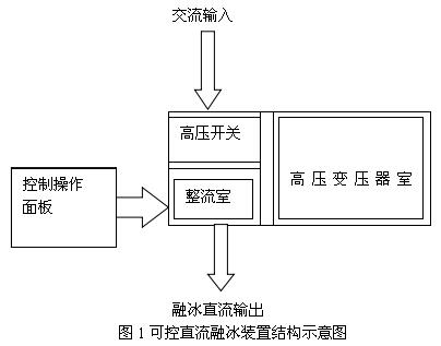
The equipment for the mobile DC inverter box, fixed in the modified special vehicles, easy to transport and use the outdoor. To meet the extreme working environment. The device structure of the device all made of high quality steel plate bending welded together. With a solid structure, nice and so on. Box "goods" shaped structure, sub-high voltage switch room, transformer room, rectifier room, the box has a right around the demolition of the door, the room with lights, easy to internal maintenance equipment. The chambers are separated from each other and are connected to each other, simple and compact, and the components are arranged in the room. The rectifying chamber is composed of rectifying elements and control components. In order to facilitate the operation of hand observation, operation buttons, measuring instruments, lights, etc. are set in the high-voltage switch room cabinet front door. The top of the cabinet is equipped with rings for the installation of the equipment. (see picture 1)
4. For the substation between the high-voltage lines, melting ice connection can be used in the following two ways to melt ice:
1) completed two times A, B, C three-phase wire melting ice
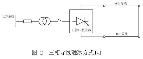
For the first time, see Figure 2, in the station will A, B two-phase short-circuit, in this site will be A, B two-phase wire connected to the DC cooling power supply of the two output, A, B phase wire ice;
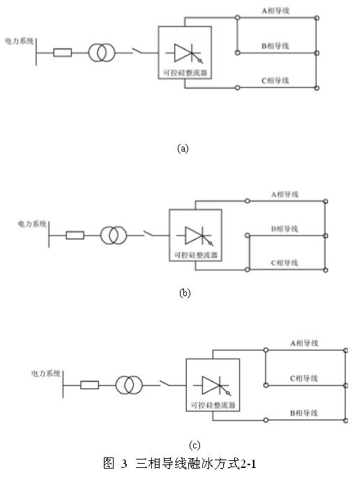
The second time in the station will A, B, C three-phase short-circuit, see Figure 3 (a), in this site will be A, B two-phase wire connected to the DC ice power supply an output, C-phase wire connected to the DC ice power supply of the other output, the melting C-phase wire melting ice.
2) three times to complete the three-phase wire melting ice.
For the first time, see Figure 3 (a), in the station will A, B, C three-phase short-circuit, in this site will be A, B two-phase wire and then connected to the DC ice power supply an output, In the site will be C-phase wire connected to the DC cooling power of the other output, the C-phase wire melting ice;
For the second time, refer to 3 (b). After connecting the A and C two-phase wires to the output of the DC cooling power supply, connect the B-phase wire to the DC cooling power supply An output, the B phase wire melting ice;
The third time, see Figure 3 (c), in this site will be B, C two-phase wire and then connected to the DC ice power supply of an output, in this site will be A-phase wire into the DC melting power The other output, the C-phase wire melting ice.
5. The device is a new and practical and effective transmission line melting ice device, to overcome the exchange of molten ice technical limitations and technical defects, has the following characteristics:
First, when the ice melt ice, the line impedance of the emotional component does not work, greatly reducing the capacity required for DC melt ice, improve the efficiency of DC melting ice.
Second, the DC melting ice voltage adjustable. By adjusting the melting ice voltage, you can meet the different length of the line of ice melting requirements, without the need for impedance matching.
Third, the base station of the DC ice-melting device can be a total station to share a set of devices, you can carry out the entire station all the line into the ice melt ice work, in the line a large area of ice, the effect is particularly evident. For some ice-covered line ice melting operation, greatly reducing energy consumption.
Fourth, the effect of melting ice significantly. The DC voltage applied to 12.5 kilovolt, melting ice current 1420 Ann, you can make the transmission wire 10 mm to 15 mm thick frozen ice melting, one and a half hours, can melt 100 km line of ice, the equivalent of 100 The workers worked for a week to knock on ice.
Rectifier cabinet mainly by the cabinet structure, the main circuit, the protection circuit and cooling system components. To ensure the high quality of the rectifier cabinet, we use a reliable technical solutions, high-quality components and advanced processing technology. We design, manufacture and inspect the equipment according to the requirements of manufacturing regulations, safety standards and IS09001 quality assurance system to ensure high reliability, easy installation, easy maintenance and easy operation.
1. DC melting device rectifier using thyristor three-phase full-control rectifier circuit, the main technical parameters:
1) Rated input voltage: AC: 3 × 10kV, 50Hz;
2) Rated output DC voltage: 2000V;
3) Rated output DC current: 500A;
4) the main circuit situation: three-phase bridge full control rectifier
5) steady flow accuracy: ≤ ± 1%;
6) Overload capacity: 120% rated transmission current overload 2 h;
7) Cooling method: forced ventilation cooling.
8) Thyristor pressure coefficient: ≥ 0.95;
9) Rectification efficiency: ≥99%;
10) Dimensions for the mobile substation box (can be customized)
2. From the application of overhead lines to meet the requirements of ice, the need for rectifier output voltage and current operating range. So should take full account of the thyristor trigger phase shift adjustment and thyristor deep control of the heat problem and the cooling system design.
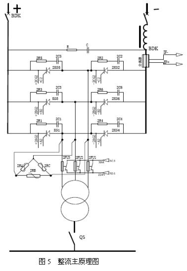
3. Rectifier cabinet structure design (see Figure 5)
1) cabinet for the anti-magnetic structure, may produce local eddy heat place, with stainless steel material cut off the magnetic circuit.
2) for the font-shaped layout, easy to open and use.
3) DC outlet: rectifier room side of the Department, to facilitate wiring
4) rectifier cabinet and rectifier control system to meet the requirements of rain and dust to prevent the external extreme harsh environmental impact of the cabinet components of the normal work, taking into account the heat problem.
5) cooling measures: the use of four strong wind cooling components and transformers. To ensure that the operating temperature is not lower than the national standard
6) rectifier cabinet and rectifier control cabinet shell color: shallow pack ash (color standard RAL7032), anti-static treatment, to ensure that the operator has personal safety.
7) All components are subjected to thermal aging and electrical aging screening, and provide test reports.
8) rectifier cabinet secondary protection with operating overvoltage, commutation over voltage, arm overheating, overcurrent, pulse loss and loss of synchronization protection. The display instrument and signal button installed in the cabinet or to ensure that easy to clear observation.
9) Rectifier arm, fast fuse arm, DC bus busbar are used high insulation performance and high strength epoxy glass support and cabinet insulation, epoxy glass support and the main cabinet of all insulation are flame retardant process To ensure the safe operation of the rectifier and the safety of the operator; reasonable over-current, over-voltage protection and good insulation with the machine has a very high reliability and security; taking into account the mechanical strength, Reduce the main circuit magnetic field impedance loss, creepage distance and rectifier components in the process of running the pressure consistency and installation, easy maintenance and other factors.
4. Rectifier cabinet fault detection and protection measures:
Rectifier cabinet with perfect fault detection and protection measures, is to improve the reliability of rectifier cabinet operation of an important part. The rectifier cabinet is equipped with the following protection function and the protection signal sent to the control cabinet for processing.
Overcurrent overvoltage protection
AC side over voltage, DC side over-voltage protection, thyristor resistance absorption absorption protection
The main circuit operates overvoltage protection. In the rectifier device into the line at the installation of varistor and RC circuit protection, when the protection system failure, send fault signal to the PLC.
Rectifier components for overvoltage protection. In the nearest rectifier components installed capacity parameters appropriate resistance element, wiring should be as short as possible, resistance absorption absorption protection.
Rectifier component fault protection. Using a quick fuse in series with the rectifier fuse fires. Fault signal sent to the PLC detection. Overcurrent protection and overload alarm. When the load current exceeds the rated value (adjustable setting) will send out the overload alarm signal to send PLC, alarm or send over-current protection trip signal.
2) bus overheating protection. When the rectifier component installed bus temperature exceeds 55 ℃, the PLC issued to the bus overheating protection and alarm signal.
3) feedback drop line fault protection. When the DC current feedback signal is open, the steady flow control system automatically into the AC feedback, and sent a feedback line to the PLC fault signal.
4) bus insulation protection. When the positive and negative busbar to ground insulation is reduced, the PLC to send bus insulation to reduce the signal.
5. Selection of major components
1) thyristor rectifier thyristor
The use of my company to introduce the production line of high-power bottom loss thyristor, the original silicon single-chip imported from Denmark TOPISIL NTD silicon single crystal material, the resistivity uneven rate of less than 10%, through 100% high temperature blocking test , The early failure of the detection element, thus ensuring the consistency and long-term stability of the rectifier component parameters. According to the railway locomotive standard to control its reverse leakage current, trigger parameters, on-state voltage drop, on-state current, more stringent than conventional industrial requirements.
2) fast fuses
The use of Xi'an Longshen fuse factory production of single-pole fast fuse, to protect the rapid, short fuse time, fast-melt resistance to test the pairing, and provide quality assurance. According to the fast-melting internal resistance parameters for group installation.
6. Digital trigger control system
CNC rectifier control system, composed of two completely independent, mutually hot standby control panel, according to the hot standby mode configuration, in the PLC monitoring, to achieve failure to automatically switch without disturbance.
The control board adopts the all-digital microcomputer trigger control system designed and produced by our company. It adopts the large-scale integrated device of DSP (high-performance digital processor) + PLC (programmable controller), with 12-bit A / D conversion, data Communication and other functions. The all-digital computer trigger control system uses dual-board structure (main control board and synchronous power board), fully sealed design, making the system more suitable for harsh environments.
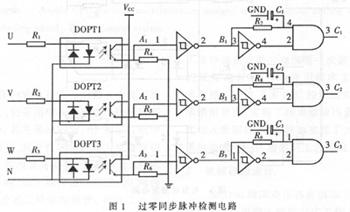
The system for the characteristics of DC melting ice, the use of zero-crossing trigger control because of the grid pollution-free, in many devices are used in this trigger. Figure 3 shows the SCR trigger circuit, using a two-level protection measures, used in multiple devices to prove that the work is stable, with high reliability.
System zero-crossing trigger, current mutation, resulting in excitation vibration, can promote the ice fall, can improve the efficiency of melting ice.
Figure 1 DOPT1 ~ DOPT3 for the AC optocoupler, Figure 1 A1, B1, C1 points of the output waveform shown in Figure 2.
Fourth, CNC rectifier technology
CNC rectifier is the core unit of the rectifier system, its reliability and stability directly affect the entire process. Control cabinet mainly by the unit steady flow control system, unit PLC monitoring system, digital touch screen composed of three parts.
In order to meet the technological development of modern electronic power equipment and the requirements of the development of on-site industrial production technology, Xiangtan Volkswagen Rectifier Manufacturing Co., Ltd. will be a long history of its technology, standardized product management, high level of design team, strict quality assurance and improvement Based on the integration of the previous rectification control system in the industrial field operation and operation on the basis of the use of advanced electronic technology at present, to ensure a high degree of reliability of the system under the premise of the successful development of the DSP (high-performance digital Processor) + PLC (programmable controller) rectifier control system.
main feature
1, the system CNC board using DSP (high-performance digital processor) + PLC (programmable controller) rectifier control mode not only because of a variety of discrete components mixed together caused by the matching problem, but also increased the storage space, So that the microcontroller system with the smallest components, designed to complete more functions. And implemented in System Programming (ISP) and in Application Programming (IAP), which has been developed for embedded programming.
2, the use of Siemens PLC technology greatly reduces the conventional relay control of the complex, simplified relay control, protection and signal monitoring.
3, the system uses a touch screen for the Chinese characters man-machine interface (touch screen can be selected by the buyer). The operator can according to the Chinese character prompts to set the rectifier system parameters, display rectifier cabinet, high and low voltage equipment, as well as the failure of the equipment to protect the same time the Chinese character display system to protect the various fault content.
The use of the system design ideas, the computer technology and rectifier full operation of the organic combination of equipment, and truly play a computer control benefits at the same time, and greatly simplifies the system hardware.
Figure:
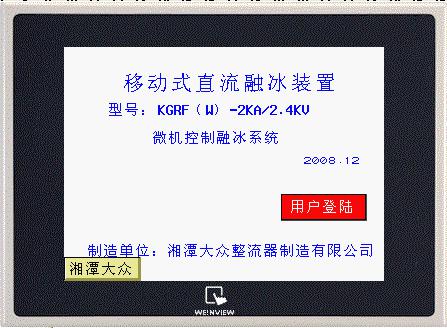
Figure 1 Operation Home
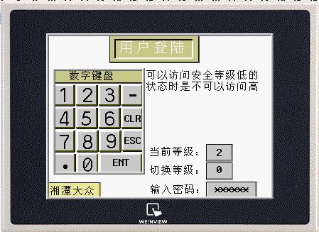
Figure 2 user login
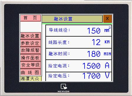
Figure 3 ice melting parameter settings
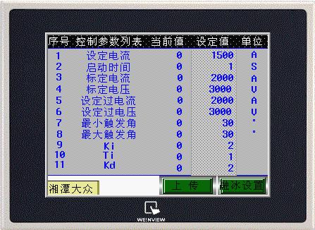
Figure 4 rectifier parameter setting
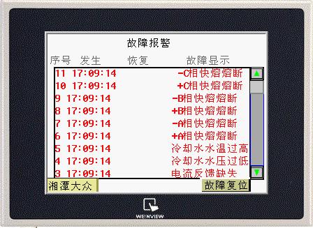
Figure 5 Alarm list
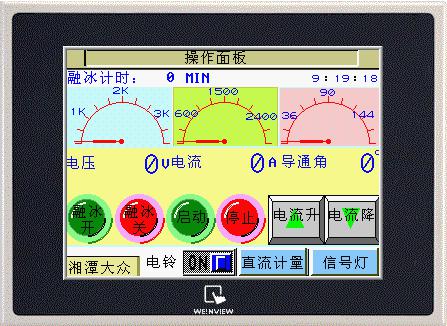
Figure 6 melt ice operation panel
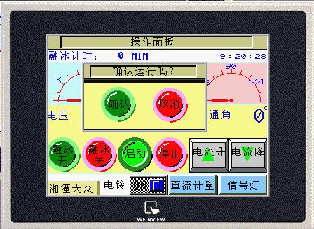
Figure 7 Run the operation
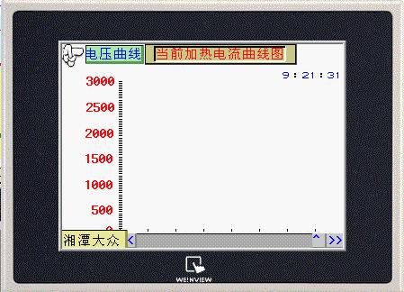
Figure 8 melting ice current voltage curve
News center
Copyright ©2017 Xiangtan public Rectifier Manufacturing Co,.Ltd Powered by www.300.cn Changsha | Mangager | 湘ICP备17009114号-1