


Product center
Contact us
Contact us
Product details
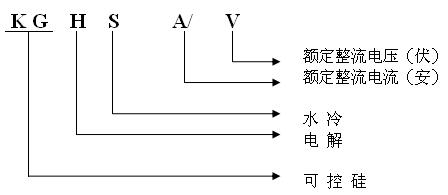
Silicon-controlled KGHS rectifier
I. General
This equipment is an energy-efficient high-current and high-power capacity integrated circuit controlled thyristor rectifier. It can be widely used in metal electrolysis of industrial aluminum, magnesium, manganese, lead, zinc, copper, tin, gold and silver for metallurgy, electrolysis of chemical salt, potassium chloride and sodium hydroxide, smelting of DC electric arc furnace, heating of graphitization chemical furnace, production of carbon, thermal treatment of copper wires and various metal wires; and electrochemical machining and DC adjustable regulated power supply needing high current and high power capacity.
The equipment provides current negative feedback and voltage negative feedback to form a closed-loop control. As clustered block elements are taken as a controller, the current and voltage stabilization precision is high. Users may select working status of current or voltage stabilization based on requirements of production process. When necessary, it is also allowed to switch into open-loop manual adjustment. The equipment is embedded with over-current and overvoltage protections. In case of any fault, the AC side may trip and give an audible and visual alarm and improve running reliability of the equipment.
Compared with traditional rectifier equipment, this equipment has significantly higher energy-saving effect and better performance. The rectification efficiency and power efficiency are optimized. It has a simple structure and is easy to trigger and control with reliable operation. It is also easy to maintain. All the elements and components are domestically produced, so with a low cost and strong practicability, the equipment is large-sized utility one which is easy to popularize.
II. User Conditions
2.1 Altitude of installation point should not exceed 2,000m.
2.2 Ambient temperature should not be lower than -10℃ and should not be higher than +40℃.
2.3 The installation place should be free of violent vibration and impact and vertical inclination should not exceed 5%.
2.4 Maximum relative humidity in air should not exceed 85%.
2.5 Ambient medium should be free of explosion hazard and serious corrosion.
2.6 Voltage waveform of AC power grid should be sine and voltage fluctuating range of power grid should not exceed ±10% of rated value.
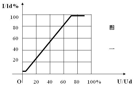
III. Main Technical Rules and Performance Indicators
IV. Outlook and Structure
The equipment is an upright type. The cabinet is made of optimum sheet steel which is bent and welded. It has the advantages of solid structure and beautiful appearance. The cabinet has double doors, which is convenient for internal servicing. All elements are installed inside the cabinet. The lower part is the rectifier transformer and the middle part is the control panel composed of silicon-controlled rectifier elements and control components. For the convenience of operation and observation, all the operating buttons, measuring instruments and indicators are set on the front door of the cabinet. A cable duct or a pad should be set under the cabinet.
V. Rectification Route and Working Principles
5.1 Route structure:
This silicon rectifier employs three-phase bridge rectifier circuit. The input is three-phase three-wire system based AC voltage 380. After various links of the route, e.g. induction voltage regulator or contact type voltage regulator, rectifier transformer and silicon rectifier cell assembly, DC power supply is obtained. To ensure normal operation of the equipment, over-current protection system and alarm system are set. See the circuit diagram for the detailed route.
5.2 Working Principles: (The circuit diagram is attached below.)
The machine realizes power grid isolation and over-load protection via three-phase AC power input and air switch QF. The contactor KM realizes button control of the equipment. The rectifier transformer isolates AC power grid and switch to a value needed and meanwhile, provides rated loading capacity. The silicon controlled switch KP1-KP6 realizes controllable adjustment of DC voltage.
5.3 Wiring: three-phase AC incoming users are connected to the incoming terminal above the air switch QF by the phase sequence of A, B and C. DC outputs are connected to loading devices by the marks of “+” and “-”. Refer to the schematic diagram for specific wiring diagram.
5.4 Grounding screws are welded at the lower part of the cabinet and provided with grounding mark. Users must well connect them to ensure reliable grounding of the equipment.
VI. Operating Procedures of Equipment
6.1 Startup
Turn the regulator potentiometer W1 anticlockwise to zero point. If water cooling system is used, cooling water must be fed. Put the “AUTO/MANUAL” switch to “MANUAL” position if manual adjustment is to be used; put the switch to “AUTO” position if automatic adjustment is used.
Close the main switch. Power indicator lights up and the blower starts to run. Press the startup button QA. The power indicator (red) goes out and the running indicator (green) lights up. There is no display on the voltage meter and ampere meter.
Slowly turn the regulator potentiometer (clockwise) until the output voltage (current) reaches value as required.
6.2 Shutdown
Turn the regulator potentiometer anticlockwise to zero point and press the shutdown button. The power indicator (red) lights up and the running indicator (green) goes out. Press the main switch. If water cooling is used, close the cooling water if the equipment is not to be used for a long time.
6.3 Debugging of equipment
Open-loop adjustment
Press the startup button QA. The power indicator lights up. Measure centralized circuit board ±15V and ±24V (up to 30V) and three-phase synchronous voltage (about 30V and 50V). If there is any inconsistency, remove fault in power supply first to ensure consistent DC power supply before next step of debugging.
Put the AUTO/MANUAL switch to MANUAL position and turn it slowly to the designated potentiometer.
Observe various levels of waveforms of trigger with an oscilloscope until pulse appears between the silicon controlled cathode and control electrode. Connect a small current analog load (10% of rated current) and observe if various phases of the DC output waves are in balance form with an oscilloscope. If not, adjust potentiometer W9, W10 and W11 (refer to the schematic diagram of main pulse).
When the designated potentiometer reaches certain value, the output may reach saturation value. To prevent saturation conduction, adjust W16 at the same time.
Connect full load and reach the above requirements.
Closed-loop adjustment
(1) After proper adjustment in open-loop condition, carry out automatic closed-loop debugging. As for automatic closed-loop, current feedback and over-current protection are mainly adjusted.
(2) Adjust W5 to change depth of current feedback (upon the requirements of users).
(3) Adjust DC voltage to at least 75% of rated value and DC current to 110% of rated value. Adjust W24 to make over-current protection circuit be actuated, then AC side trips, bell rings and over-current indicator lights up. Then adjust the nearby designated potentiometer to zero point and restart to resume a normal circuit.
VII. Precautions
1. System debugging and adjustment have been done before the equipment leaves the plant, so the equipment complies with technical requirements. There is no need to adjust it before use.
2. Check the machine and elements and components before installation and check if any tightening screws become loose or damaged.
3. Do not make a mistake in the input phase sequence and polarity of output line during wiring; otherwise, there might be short-circuit accident or equipment damage.
4. Installation place of the equipment should comply with use conditions as required. There should be adequate distance between the cabinet and surrounding structures (e.g. wall) for the convenience of operation and inspection.
5. Prevent inversion and violent vibration of the equipment during installation and hoisting. Check elements and components (including screws) inside the cabinet thoroughly after installation to ascertain if any of them are loose, shed or damaged for vibration and impact or affected with damp during transportation. If any, take necessary actions.
6. The equipment has been tested and debugged before leaving the plant. However, it is still necessary to conduct no-load and light-load test before putting it into use to verify whether the equipment is intact and well-conditioned.
7. Make an overhaul regularly of the equipment during normal operation. Normally, it should be shut down and overhauled once a quarter to remove dirt inside the cabinet and check whether the elements are well conditioned.
8. As overload capacity of silicon elements is low, it is not allowed to use the equipment in overloaded condition for a long term.
9. When any element is damaged, it is required to replace another one of the same specifications and model.
10. Where the equipment is not to be used for some time, package it and put it at a dry place indoors.
News center
Copyright ©2017 Xiangtan public Rectifier Manufacturing Co,.Ltd Powered by www.300.cn Changsha | Mangager | 湘ICP备17009114号-1